Spherical Robot
Introduction
Spherical bots are great way of surveillance due to their better mobility compared to other bots due to its rolling motion. They are highly beneficial for military purposes as they can provide live video feed of the surrounding land(where it is dangerous to enter) to the military base from which it is controlled through remote communication. It can further provide audio feed and help in mapping its location so that the controlling unit will be able to locate it whenever required(in case of any casualty or so). Spherical bots have advantage over aerial bots economically and are better to use for small-scale surveillance. Also they can be given the “disguise” attribute or “camouflage” by using special fluids.
Current scope of the bot
- Remote controlled Locomotion(by joystick)
- Live video stream capturing the surroundings in which the bot moves
Locomotion
As mentioned earlier, the bot can be moved around with remote-control using a joystick. This is done to make the bot move around to get the video feed.
Components required:
- Two axis joystick module
- Arduino Uno(x2)
- nRF24l01 module(without antenna)(x2)
- jumper wires (female-female, male-female, male-male)
- L298N motor driver module
- DC BO motors(x2)
- wheels (x2)
- Servo motor
- Weights
- 6V battery
Implementation:
There are two units in Locomotion part:
- Control Unit
- Motion Unit
Control Unit:
The aim of this unit is to take input from the joystick in the form of an array which contains the input for both DC motors and servo motor(since it is a two axis joystick). So first let us understand the dynamics associated with the bot(till our current work): The entire Locomotion unit circuit is placed in the interior of the transparent sphere and is held steady by acrylic sheets. To both the ends of the locomotion unit circuit are connected two DC motors which are further mated(revolute mate) with the wheels. The wheels are attached to the sphere using a double-sided tape. So, even if the motors are provided with power and wheels are rotated, the internal circuit remains stationary and the sphere that is attached to the wheels alone rotates with the wheels. One of the axis of the joystick takes the readings for the speed of both the motors which means both the wheels move with the same speed. Then how will the bot tilt to the right or left or take a turn? This is accomplished with the help of servo motor which is connected to weights. If the servo motor is turned in such a way that the weights tilt to the right or to the left, then the center of mass of the bot changes accordingly which changes the orientation of the bot. With the help of this, we will be able to turn the bot to the right or left. So, the another axis of the joystick is gives the angle which the servo motor should move. For example, if u move the joystick along its x-axis, both dc motors move depending on the angle through which the joystick was turned. If the axis is not turned at all, the motors won’t rotate or even tend to rotate(since there will be a minimum power requirement for the motors to work). If u move the joystick to the positive end, the motors move forward and if u move it to the negative end, they rotate in the reverse direction with their speed depending on the position of the joystick. Now the rate at which the speed of the motors changes depends on the rate at which u change the position of the stick.
Now, the position of the stick relative to the other axis gives the angle of the servo which will be its input. If the stick is not moved wrt y axis, the servo motor shaft will assume its initial position(90 degrees). If the stick is moved to one extreme of the axis, the position will be 0 degrees and for the other extreme, it’ll be 180 degrees.
If the joystick position is 45 degrees wrt both the axes in then positive sense, the bot would turn to the right and so on…
The next is the circuit part: The data from the joystick(input on both the joystick axes) is sent to the Arduino Uno in the Control unit. Uno transmits this data in the form of an array through the nRF24l01 module at the control unit which acts as the transmitter(TX) for the entire “Locomotion Part”. The data from the joystick is sent to the Arduino Uno in the ‘Control unit’ through SPI communication which is a wired protocol to transmit data synchronously between a “Master” and a “slave” which in this case are “Uno” and “nRF24lo1” respectively.
Here’s the circuit for the Control Unit of the Locomotion Part: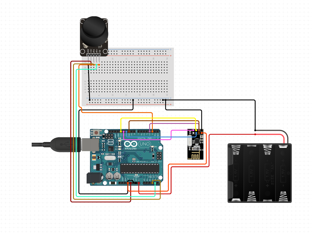
Motion unit:
The data sent by the TX is received by another such nRF24l01 module present inside the bot which acts as RX for our “Locomotion Part”. This data is then sent to the Arduino Uno in the bot(again SPI protocol) which then sends the actuating signals to the motor and the servo that allow the locomotion.
Here’s the circuit for the Motion Unit of the Locomotion Part: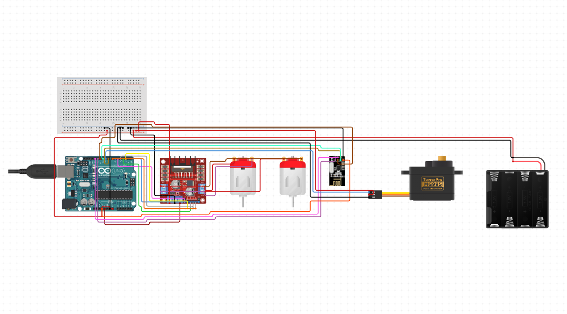
Video Stream
Components required:
- esp32 camera module
- Jumper wires
- Arduino Uno R3
- 9V battery
Esp32 camera module is connected to the arduino uno(any other FTDI module can also be used) so as to get the live video feed. This video is transmitted over WiFi which can be viewed on a media player using a static live stream URL which is generated after the code is uploaded to the esp32 camera module.
Assembly of the final bot
There are two parts in the bot:
- Internal structure: The one that comprises of the circuit to be placed within the sphere. The circuitry is held by two acrylic sheets one below the other.
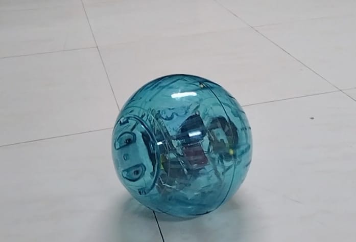
- External structure: The hollow sphere comprises this part.
Check the following CAD model for gaining a better understanding of the two layers of internal structure:
There are two layers in the internal structure of the bot each having acrylic sheets as their base:
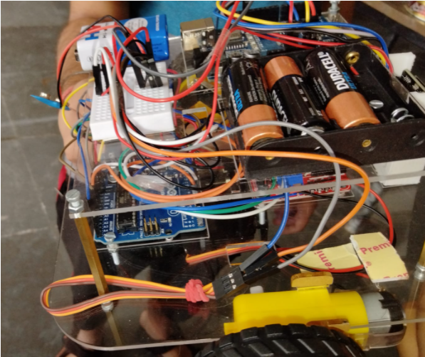
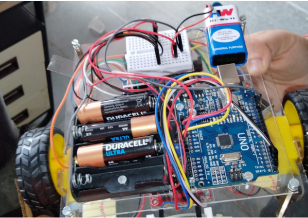
- Top Layer: This consists of an Arduino(which is to be connected to the esp32 for capturing video feed), a 6V battery consisting of 4*1.5V cells which is used to power up the locomotion motion part, a breadboard, a 9V battery to power the Arduino connected to the esp32.
- Bottom Layer: Consists of the L298N motor driver, Arduino which is connected to the RX nRF24l01, the RX nRF24l01, esp32 camera module, servo motor, dc motors, wheels attached to the dc motor. There is also a hanger that is attached to the servo motor for carrying the weights(This is used to displace the center of mass of the system which tilts the bot either to the left or to the right ). There is also a esp32 holder. The last two components i.e., the hanger and the holder were 3D printed acc. to our purpose.
The top layer is held on the bottom layer using metal spacers, screws and bolts. The wheels are attached to the sphere internally using double sided tape and hence, both the hemispheres are brought together and locked to finally complete the spherical bot.
The following pics show the internal structure:
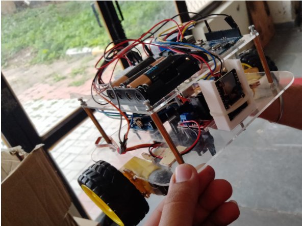
The final bot looks like this after the assembly:
Shiva Rudra Lolla
Robotics Enthusiast
My research interests include autonomous systems and perception. Drop me a message if you want to connect!